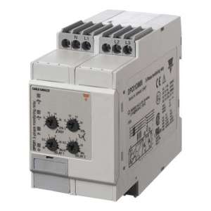
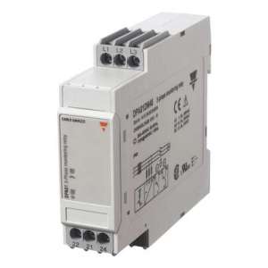
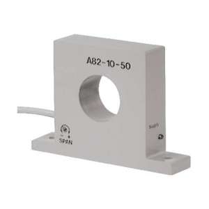
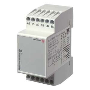
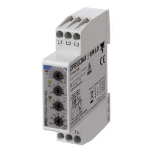
DIC01DB23AV0, Control and Protection Relays Single-phase AC/DC Max/Min Current Control, TRMS Models DIC01, PIC01, DIC01DB23AV0, Relays for precise control of maximum+minimum, maximum+maximum or minimum+minimum AC/DC voltage and current levels (selectable by DIP switches). The DIC01 can also make positive/negative DC measurements by interconnecting terminals Z3 and Y1. These relays can be connected to current transformers models MI or MP and A82 or E83. Both models have two independent setting levels with their own switch-on delay. Only in the case of the DIC01 each setting level can operate with only one SPDT relay. Its latching function allows to keep the relay output activated. The inhibit function is used to prevent the relay from operating when necessary (maintenance operations or adjustments). LEDs indicate the status of the alarm and output relays., DIC01DB23AV0, The DIC01 and PIC01 relays control AC and DC voltages and currents. The DIC01 model can also monitor positive and negative DC voltages by connecting terminals Y1 and Z3. Example 1 (Non-contact input - min. + max. voltage - 2 SPDT relays normally energized (1 SPDT relay for PIC01 model) - True RMS, TRMS) DIC01: A relay switches on when the voltage remains below the preset minimum voltage value for a time longer than the set delay period. It switches off when the voltage exceeds the preselected level plus the adjusted hysteresis. The other relay switches on when the voltage exceeds the preset maximum voltage value for a time exceeding the corresponding delay period. It switches off when the voltage drops below the selected level minus the hysteresis. PIC01: The relay switches on when the voltage remains below the preset minimum level for a time exceeding the corresponding set delay period, or when it exceeds the preset maximum voltage level for a time exceeding the set delay. The relay switches off when the voltage exceeds the preset minimum voltage level plus hysteresis and when it falls below the preset maximum voltage level minus hysteresis (the hysteresis is the same for both levels). Example 2 (Active latching function - min. + min. current - min. + max. current) - 2 SPDT relays (1 SPDT relay for model PIC01) - true RMS, TRMS) DIC01: Each relay switches and latches when the current falls below the selected level for a time longer than its corresponding set delay period. Whenever the current exceeds the preset level plus hysteresis, each relay will cut out when the contact input connection is interrupted. PIC01: The relay switches on when the current remains below the selected maximum level for a time exceeding the set delay period. Whenever the current exceeds the preset maximum level plus hysteresis, the relay will cut out when the contact input connections are interrupted. Note Different time delays can be used for the preset values. Example 3 (Inhibit function active - max + max current with CT type MI - DPDT relay (SPDT for PIC01) - true RMS, TRMS) Whenever the contact input connection is interrupted, the relay will cut in when the current through the current transformer MI exceeds the preset minimum level for a time longer than the set time delay. It will trip when the current is below the minimum level minus hysteresis or when the contact input terminals are interconnected. Example 4 (Inhibit active function - max.+max. current with CT type A82-10 - DPDT relay (1 SPDT relay for PIC01 model) - true RMS, TRMS) Whenever the contact input connection is interrupted, the relay will cut in when the current through the current transformer A82-10 exceeds the preset minimum level for a time longer than the set time delay. It will cut out when the current remains below the preset minimum level minus hysteresis or when the contact input terminals are interconnected. Example 5 (DIC01 only) (no contact input - min.+max. voltage - 2 SPDT relays normally energized - DC positive/negative) One relay will cut in when the voltage remains below the selected min. voltage for a time longer than the set delay period. It will trip when the voltage exceeds the preset level minus the hysteresis. The other relay will cut in when the voltage exceeds the preset maximum voltage for a time longer than the set delay period. It will trip when the voltage drops below the preset level minus the hysteresis. In this case the spare front panel label must be placed on the equipment for correct level setting. Note When the inhibit contact is open and the input signal is in alarm position, the relay(s) will not activate until the delay period has elapsed.

No customer reviews for the moment.
Or Insert your account information: