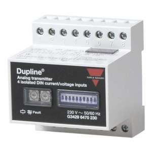
G34296470024, Universal Analog Input Module for DIN signals Model G 3429 6470, G34296470024, Universal Dupline® Analog Input Module with 4 inputs for external power supply. The analogue values of the inputs are converted into digital values which are transmitted by the Dupline®. Each input is isolated to avoid ground loops and to simplify installation. Each input type can be selected as 0-20 mA, 4-20 mA or 0-10 VDC and different analog input types can be combined on the same input module. The transmission format of the Dupline® can be selected to adapt the input module to existing installations, or simply to use the best combination of resolution and speed. The formats are: 8 bit binary, Analink and 3 1/2 digit BCD (with or without multiplexing), G34296470024, The G3429 6470 is a universal analogue input module with 4 inputs. Each input can be individually configured to measure voltage or current. The transmission format is selectable and supports all Dupline® analogue protocols: Analink, 8 Bits or 3 1/2 digits in BCD. Coding is done only by the built-in dip and rotary switches, so the GAP 1605 programmer is not required. Referring to the diagram on the previous page, the setting of the module should be done as follows: Note that no signals should be applied to the inputs before the correct mode (current or voltage) has been selected using the 4 shunt switches at the top. Set the scale of each input (0/4-20 mA or 0/2-10 V) with switches 1-4 on the front panel, and select the number of inputs with switches 5 and 6. The module only accepts Dupline® addresses according to the number of inputs enabled, and the selected trans- mission protocol (mode) with switches 7 and 8: If all 4 inputs are enabled, the module will use 4 Dupline® channels in consecutive order, starting with the address set on the two rotary switches on the front panel. Example: The setting of "D7" indicates that input 1 transmits on Dupline® channel D7, input 2 on D8, input 3 on E1 and input 4 on E2. Address assignment for 8-bit binary protocol: If all inputs are enabled and non-multiplexed mode is selected (switch 9), the module will use four Dupline® channel groups (32 channels) in consecutive order, starting with the group set on the first rotary switch (A-P). The second rotary switch (0-F) is not used in this mode. Example: The setting of "F" on the first rotary switch indicates that input 1 transfers into Dupline® channel group F, input 2 into G, input 3 into H, and input 4 into I. If the multiplex mode is selected, the module will use one Dupline® channel group (8 channels). The first rotary switch (A-P) is used to set the group and the second switch is used to set the multiplexing direction to be used by the first input, no. 1. Example: The setting of "F" on the first rotary switch and the setting of "0" on the second rotary switch indicates that input 1 transmits in Dupline® group F mux. address 0, input 2 in group F mux. address 1, input 3 in group F mux. address 2 and input 4 in channel F mux. address 3. Address assignment for 3 1/2 digit BCD protocol: If all inputs are enabled and non-multiplexed mode is selected (switch 9) the module will use four Dupline® channel groups-pairs (64 channels) in consecutive order. The first rotary switch (A-P) is used to set the start-up pair-group. The second rotary switch (0-F) is not used in this mode. Example: The setting of "C" or "D" on the first rotary switch indicates that input 1 transmits on Dupline® channel pair C-D, input 2 on E-F, input 3 on G-H and input 4 on I-J. If multiplexed mode is selected, the module will use a Dupline® channel pair (16 channels). The first rotary switch (A-P) is used to set the pair-group and the second rotary switch (0-F) is used to set the multiplexing direction to be used by the first input, no. 1. Example: If "C" or "D" is selected on the first rotary switch and "8" on the second rotary switch, it means that input 1 transmits in Dupline® group C-D mux. direction pair 8, input 2 in group C-D mux. direction group 9, input 3 in group C-D mux. direction group A and input 4 in group C-D mux. direction group A and input 4 in group C-D mux. direction group B, which means that input 1 transmits in group C-D mux. direction group 8 of the Dupline®. A and input 4 in group C-D mux. address group C-D mux. B. Note The selected transmission protocol is valid for all enabled inputs. The module cannot transmit different protocols at the same time. Analogue transmitters must not be used in systems with installed channel generators with 2 or 3 sequences

No customer reviews for the moment.
Or Insert your account information: