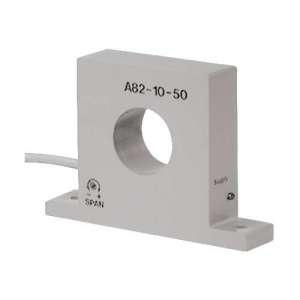
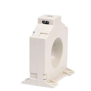
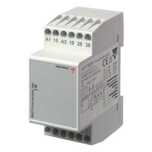
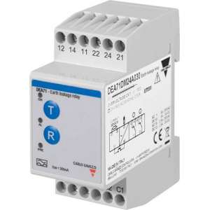
PWB02CM2310A, Control Relays and Protection Three-phase Active Power Control Models DWB02, PWB02, PWB02CM2310A, These relays allow precise control of active power (TRMS measurement) in three-phase systems with balanced load. They are used to control the load of asynchronous motors and other symmetrical loads, as well as the power consumption of the system. The start/stop input allows a manual switch to be used to start and stop the system without the need for any auxiliary device. The interlocking function allows the relay to be kept activated even after the alarm condition is over. The inhibition function is used to prevent the operation of the relay when necessary (maintenance operations or adjustments). The LEDs indicate the status of the alarm and the output relay. , PWB02CM2310A, The DWB02 and PWB02 devices measure the active power of a three-phase system with balanced load. To avoid the detection of overloads during engine start-up, the relay has a delay to the adjustable connection. Example 1 Interlocking mode, relay normally activated. In this case, the DWB02 or PWB02 equipment is connected to a three-phase asynchronous motor through a standard intensity trafo or the MI model ..., (connected between terminals U1 and U2). When the supply voltage is applied, the relay connects, and after the delay to the adjusted connection, the equipment begins to measure the power. If this is within the established limits, the relay is kept connected and the yellow LED lights up. If the power is above or below the set limits, the relay disconnects when the adjusted time period has ended. To restart the measurement, connect the Z1 and U1 terminals (2 and 9) or interrupt the supply voltage for at least 1 s. Example 2 Non-interlocking mode, relay normally activated. The DWB02 and PWB02 react the same as in the previous example, only in this case the relay is automatically reactivated when the active power is again between the two established limits. When the measured power exceeds the adjusted max. value, the red LED starts flashing, and the output relay disconnects after the adjusted time period. When the measured power is below the adjusted min. value, the red LED starts flashing, and the output relay disconnects after the adjusted time period. Example 3: The DWB02CM2310A and PWB02CM2310A can be used to control the power of a single-phase load with mains voltages from 208 to 240 WLA. In this case, the supply voltage must be connected between terminals L1, L2 (or 5, 6); and terminals L2 and L3 (or 6 and 7) shall be interconnected. Example 4 Start/stop mode, relay normally activated. In this case, the DWB02 or PWB02 equipment is directly connected to a three-phase asynchronous motor. When applying the supply voltage, the relay connects and the start/stop contact closes. Once the delay to the adjusted connection is over, the equipment begins to measure the active power. If it is within the programmed limits, the relay stays connected. If it is above the max limit or below the min limit, the relay disconnects, lighting up the red LED when the adjusted delay time has ended. The relay disconnects immediately when opening the start/stop contact. To restart the system, simply close the start/stop contact.

No customer reviews for the moment.
Or Insert your account information: