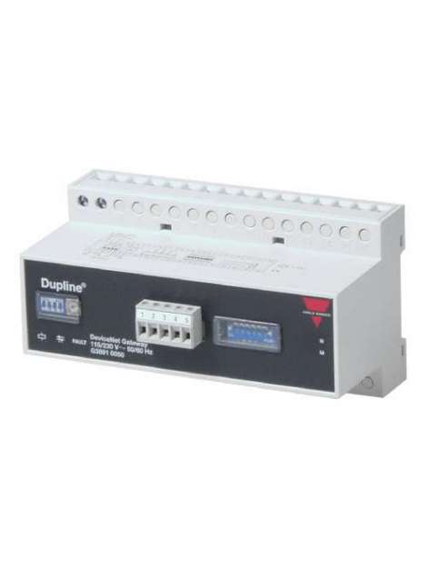


G38910050230, Dupline® DeviceNet Gateway Type G 3891 0050, G38910050230, Dupline® Channel Generator with the function of a DeviceNet slave. This means that the 128 Dupline® I/O’s can be read/controlled by DeviceNet masters (PLC’s, PC interface cards, etc. from various suppliers). Several Dupline® gateways can be connected to the same DeviceNet network., G38910050230, The Dupline® DeviceNet Gateway is a Dupline® Channel generator with a function of a DeviceNet slave. This means that the 128 Dupline® I/O’s can be read/controlled by DeviceNet masters like PLC’s and PC interfacecards from many different suppliers. Several Dupline® Gateways can be connected to the same network and operate together with other DeviceNet modules like operatorpanels, MMI’s I/O modules etc. Configuration switches The unit is equipped with the following configuration switches. (See also switch settings) 1x16 position rotary-switch for selecting Number of Dupline® Channels in the range 8..128 (in steps of 8). The selected letter indicates the last channel group available on Dupline®. If e.g. H is selected, the 64 channels in groups A..H will be available. 1x DIP-switch for selection of Dupline® Operation Mode. In “Normal” mode, Dupline® operates as a peer-to-peer system where the channel generator automatically establishes a connection between Dupline® inputs and Dupline® outputs which are coded to the same Dupline® address. If e.g. an input coded for B5 is activated, the output(s) coded for B5 will also be activated. Consequently, a Dupline® output can either be activated through the output-data received on DeviceNet or by an active Dupline® input coded for the same Dupline® address. In “Split I/O” mode, the Dupline® inputs and Dupline® outputs are treated independently by the channel generator. If e.g. and input coded for B5 is activated, the Gateway will make the information available on DeviceNet (like in normal mode), but it will not automatically activate the Dupline® output(s) coded to B5. The Dupline® outputs are controlled exclusively through the output data received on DeviceNet. 1x DIP-switch for selection of analog data. In OFF position only Digital In/Out data are transferred. To enable analog data-I/O handling this DIP-switch must be ON. 1x DIP-switch for selection of Analog input operation mode. When OFF the analog input data are read as AnaLink. Each channel from C1 to P8 are read as 8 bit analog data. When ON the analog input data are considered as 3 1/2 digit multiplexed data. The multiplex-control (Synchronization) are automatically set to operate on channels A1..A4 which then can not be used for other purposes. 1xDIP-switch for selection of Analog Output operation mode. When OFF the Analog output are emitted as AnaLink. When ON the Analog Output-data are emitted as 3 1/2 digit Multiplexed data, and channels A1..A4 will control the multiplex addressing . Dupline® Input Data A part of the Gateway inputprocessor reads all the 128 Dupline®-channels as Digital inputs (16 bytes) and another part reads the 112 channels (C1 to P8) as Analog inputs and performs the appropriate scaling of input data. Each Analog value are represented as a 16 bit word with MBS as sign and 15 bits of magnitude. This results in a total of 224 bytes contaning all analog input-data. All data are mapped with Digital input bytes starting at relative address 00 followed by the analog data. See In/out data mapping. Dupline® Output Data Digital Output data are handled in accordance with the Dupline® Operation Mode: Split I/O or Normal. Analog data are handled and scaled in accordance to Analog Output operation mode. When Analog Output is selected, care should be taken to avoid a mix of Digital and analog output data. The AnaLink Outputs a series of pulsating 1’s and 0’s and for the value of zero, a basic 8 pulse-train will be outputed, for enabling the receivers to detect validity. When outputting Multiplexed Analog, two bits are output for format-check. To disable analog outputs, write a value of -32767 (0xFFFF) in all locations where only digital data should be. If eg. channels O1 .. P8 are desired as purly digital data, all analog data bytes mapped from relative address 0xD0 to 0XEF should be written the value 0xFF.
No customer reviews for the moment.
Or Insert your account information: